

Interactions

Simulating the Spectrum of the Ripple-Voltage
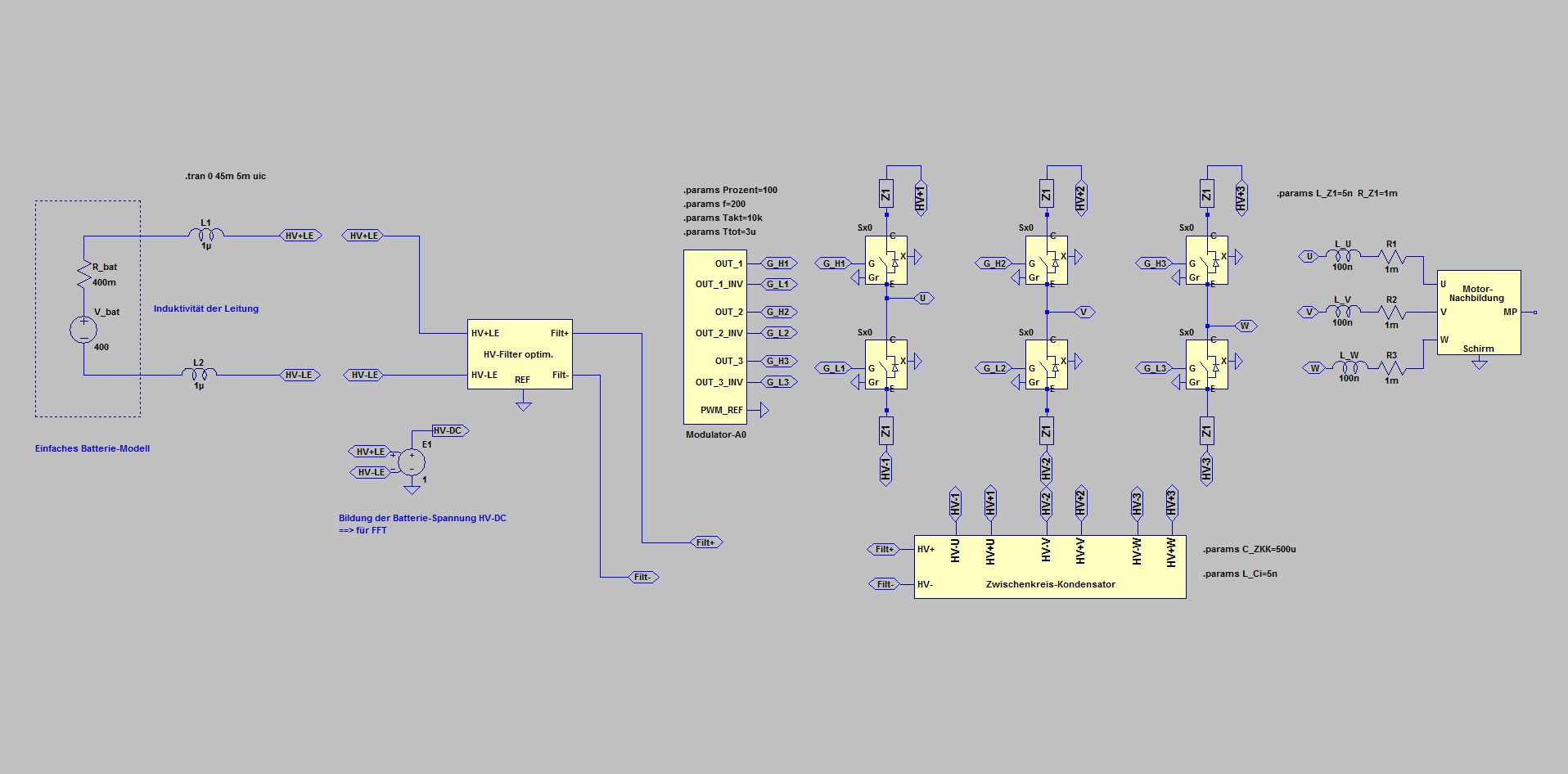
In the present simulation, the modulation is 100%, the rotation frequency is 200 Hz (= 3000 rpm for a 4-pole machine)
This results in a peak current of about 1000 A and an effective value of about 700 A
Combining HV-LE and HV + LE to HV-DC (the battery voltage at the inverter port) provides a variable for the FFT
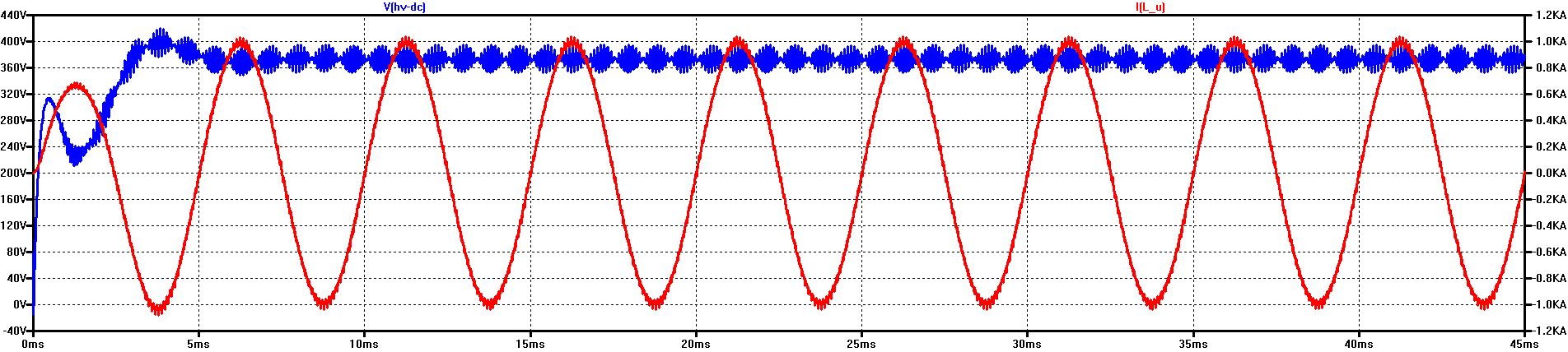
The battery voltage with the Ripple-Voltage on the HV-line and the corresponding phase-current
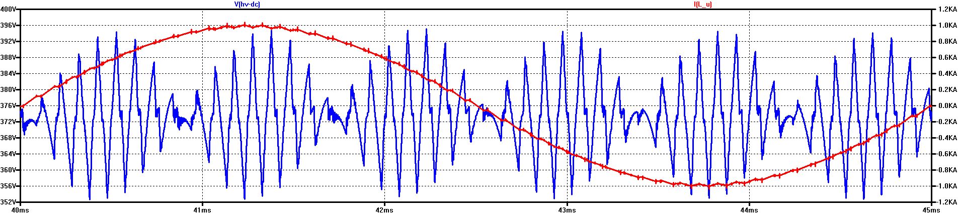
The battery voltage with the Ripple-Voltage on the HV-line and the corresponding phase-current - zoomed
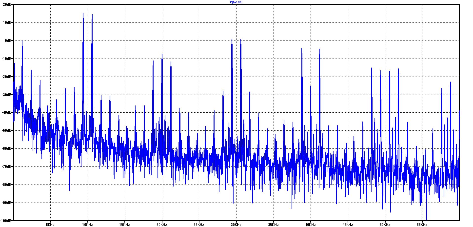
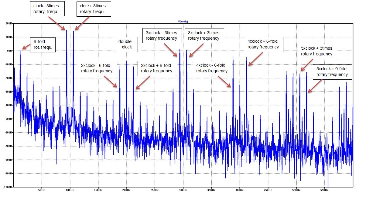
Spectrum of the Ripple-Voltage at 200 Hz rotary frequency and 10 kHz switching frequency
Spectrum of the Ripple-Voltage at 200 Hz rotary frequency and 10 kHz switching frequency
In the diagram the frequencies of the most important interference lines are marked - and provided with their mathematical assignments
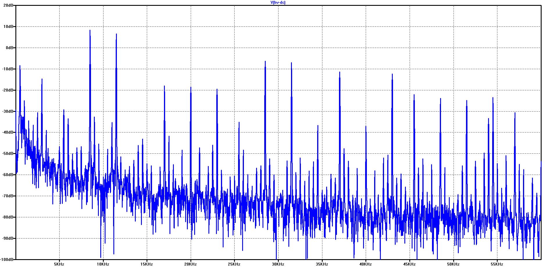
Spectrum of the Ripple-Voltage at 300 Hz rotary frequency and 10 kHz switching frequency
Due to the higher rotational frequency, the interference lines move further apart
Spectrum of the Ripple-Voltage at 500 Hz rotary frequency and 10 kHz switching frequency
Due to the higher rotational frequency, the interference lines move even further apart
Theoretically, there is no vacant location where there would not be a spectral line, if the rotational frequency can cover a wide range. However, the maximum possible amplitudes above the corner frequency for field weakening decrease with increasing rotational frequency, so that the excitation in these regions is lower.
© Ingenieurbüro Lindenberger 8447